
Our cameras are ready and added to our project in Modulo Kinetic Designer.
Now, we will add and calibrate them in order to place them in the 3D environment.
Use the Wand to get points for the calibration
- Put the Wand onto its stick to make higher movements
- In Modulo Kinetic Designer, select the group “TRACKING”
- In the Editor tab, change the mode to Calibration

- Then press Play
- A pop-up window asks if you are sure to process the calibration. Press OK

- The cameras in the group should now be green, and should physically have their front ring red
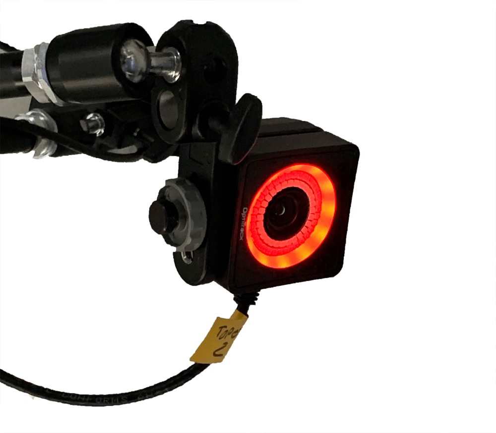
- Power on the Wand

- As soon as the cameras will see the three LEDs on the Wand, the cameras ring will turn green
If the camera ring is yellow or red, it means it does not see the 3 LEDs of the Wand.
- Move everywhere while doing movements with the Wand in order to cover all the scenic space
Keep in mind that the more movements you will do, the more precise the calibration will be.
- Go to Calib. report to see how many calibrations points you got
- When you have enough points, click on the Stop button
- After the calibration, the Calib. report gives you a report of the calibration results

Check that the LEDs are well tracked by the cameras
- In the General tab, switch the mode to Tracking, then press the Arrow button
![]()
- You can switch the Visualization to Points in the cameras views window to see the ID of the LED which is sent by the Beacon

- We can check in the Listing tab as well if we see the LED with its ID
Calibrate the Ground position
- To achieve this, we use the KineMotion Square tool
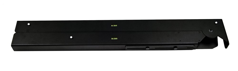
- Place the Square on the floor. X axe will be defined by the shortest branch of the Square, meanwhile the Z axe will be defined by the longest one

- Select the group “TRACKING”
- In the General tab, select Tracking mode and press Play
- Go to the Listing tab to check if Modulo Kinetic Designer sees the Square’s points

- Go to the Ground calib. tab
- Be sure to uncheck the Enable ground calibration in order to do the square calibration
- Select the Ground plane type. If you own the KineMotion kit, It is the Official Modulo Pi
- Then, click on Calibrate

- The grey values Corner-Smallest distance-Largest distance should get updated
- To see how your cameras are set once the Square calibration is done, open the 3D Viewer
- Be sure to check the Enable ground calibration box

- When it is done, you can remove the Square from your stage
Link a 3D object as a Sphere to the LED point
- First, stop the tracking py pressing the Play button
![]()
- In the 3D Scenes, add a Sphere
- On KineMotion, select the tracking group, go to the Listing tab, and note the ID of the LED

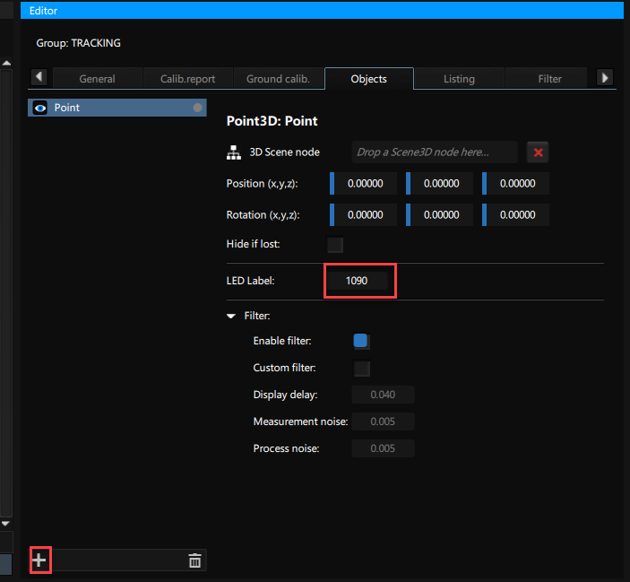
- Open the Objects tab, click on + to add a Point
- Fill the ID number with the one you noted on the Listing tab. In our case, it was 1090
- Then, drag&drop the Node_Sphere to 3D Scene Mode field

- On the 3D Viewer, you should see the Sphere moving as your LED point tracked on your stage.

Need more help with this?
Don’t hesitate to contact us here.