
The Digimap tab allows you to take control of some media layers in the timeline or 3D parameters from a sensor or an external device.
This way, you can add interactivity to your show.
For instance, you can move a panel on a stage (with the projection moving along with it).
You can also change the layer opacity from a lighting control, or control your show from a custom OSC control panel, etc.
Add a new Digimap by clicking on the + button.
Select a list of Digimap and click on the trash button to delete a selection of Digimap.
You can click on the eye button to enable/disable a Digimap.
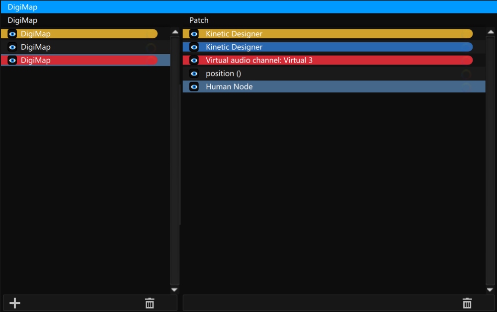
Digimap editor:

Trigger:
Drag& drop a device in the trigger area to be controlled from incoming values of this device.
Check in the device list if you can use this device as a trigger in a digimap.
Patch:
Once your trigger is selected, you can create a patch to take the control of the parameters with this digimap: just drag&drop a parameters of the timeline, a 3D node from the 3D scene in the patch list.
Select a list of patchand click on the trash button to delete a selection of patch.
You can click on the eye button to enable/disable a patch.
Digimap calibration:

In order to program the trigger, you will need to calibrate the incoming value (In A) which is the starting point; and the incoming value B (In B), the end point.
Then you will have to assign a value (i.e. media position in pixels) as a starting point, and a value for the end point.
Once this is done, it will generate 2 new values: The Offset (in pixels) and the coefficient.
The following example shows the steps for the calibration of a media projected on a moving panel using a Rotary IP device to trigger:
Once you have assigned the media on the Patch tab, go to the trigger tab to calibrate the media accordingly to the Rotary values.
• Click on the trigger bar to select a device to trigger: Digimap 01, will be triggered by the Rotary-IP01
NB: In order to cover a smooth tracking of a panel on which we want the media on the first layer of the first timeline to follow, we will have to calibrate the maximum distance possible between the Start position A and the End position B.
• Move the panel physically on the Start position (A)
• Simulate the encoder’s value in position (A)
• Select 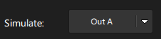 in order to calibrate the Start position
• Click on the ![]() to set a Starting position encoder value
to set a Starting position encoder value
• Now, simulate the A point in pixels: Move with the mouse on the white box to calibrate and set the Out A
• Then, return back to 
• Now, move the panel physically on the End position (B)
• Select 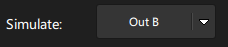 to calibrate the end position
• Click on the ![]() to set an Ending position encoder value
to set an Ending position encoder value
• Now, simulate the B point in pixels: Move with the mouse on the white box to calibrate and set the Out B
• Then, go back to
• Once the Start and End position are calibrated, click on 
This action will set a *new Offset*and a *new Coefficient *value.
The Digimap process is over. Test it by moving the panel.
Digimap filtering:

It’s possible to filter a too jerky incoming signal or to try to compensate a little bit some delay. It’s difficult to explain how to move the process, mesurement and error cov: the best is to try .. Regarding the delay: adjust the value to compensate the delay : if it’s a too big value, you will be in advance, a too low value, you will be late, …
Javascript:
It’s possible to create a javascript to do custom things on the incoming value (for example you want to have a non linear relation between the incoming value and the output).
See this example :
value is the incoming value and you need to return the result at this end.
For math function don’t forget to Math. before the function (for example Math.cos)

Need more help with this?
Don’t hesitate to contact us here.