
Photo of the calibration pattern : public point of view
A photo should be taken from the general point of view.
This photo must be adjusted to match the ratio and resolution of our projectors using Photoshop Crop tool. And possibly correct the paralaxes generated during the shooting.
Firstly it is necessary to determine the projection area. For that, we have to define the size of the Photoshop file according to the resolution of our projectors (We have two 1920 × 1080 HD projectors).

Photoshop and PSD file Resolution.
By importing the photo in Photoshop we can configure the calibration pattern file size.
• Go to Image/Image Size, in order to work on a fixed size, make sure the padlock is locked (this will maintains the image ratio) and enter 1920 pixels width.
The height changes relatively to the width to match the new image size.
• Click OK.
Note the new height.
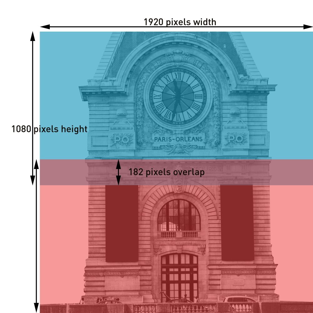
To match its size to 2 projectors of 1920×1080 pixels resolution, we must calculate overlap.

Calculating Overlap
If our project did not have overlap; the pixel workspacespace for 2 projectors would be two times their height in pixels, which is equal to 1080*2 = 2160 pixels.
Our photoshop file has a height of 1978 pixels. So the overlap is: 2160 – 1978 = 182 pixels.
Characteristics of the PSD file

You will have to create :
-A folder named OUTPUT.
This folder contains all the Outputs of your project. Each Output is a single layer layer.
-A folder named MAP.
This folder contains all the layers of the X-Map and masks. Each shape is a single layer.

Output layers
To create the future outputs of the Modulo Kinetic, you have to create rectangles shapes that correspond to the ratio of your video projectors (in our example 16/9).
For this you can use the Rectangle tool of Photoshop.

Each shape corresponds to the desired projection area of a projector.


At last, the vectorial shapes must be pixelized (right click on the layer then choose Rasterize Layer).

Map layers
Use all the Photoshop tools to isolate all the significant elements of the facade and create a layer for each element.
Start with relatively flat areas, and then the decorative elements.
We advise you to follow the following order:
- major background surfaces ( top, bottom, full )
- big elements of the façade (door, window, column…)
- details of the façade
Every element should be cutout and filled with a single solid color.
For semi opaques elements ( like windows) it is advisable to select a black solid color. In order to turn the X-Map into a mask if necessary.
It will be useful to split each element overlapping on several outputs at the same time. One part for the top part of the projection and a second for the bottom part.
This will make it easier to adjust the warp of each X-Map.
Importing The PSD file in Modulo Kinetic
Now we are ready to import the PSD file in Modulo Kinetic.
Outputs will automatically be created according to the layers in the OUTPUT folder of Photoshop.
X-Maps will be created in the corresponding outputs according to the layers present in the MAP folder of Photoshop.
You can download the PSD file here: Xmap_facade_landscape
For more informations about X-Map see X-Maps
You can save a copy in .jpg or .png format with the X-Map layers filled with bright colors and place it in the Modulo Kinetic timeline.
This will be useful to set the warp of the X-Maps.
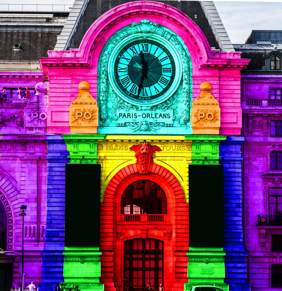
You can download the colored pattern here: colored-pattern
Need more help with this?
Don’t hesitate to contact us here.