Categories
- GPU Blend
- GPU Blur
- GPU Color
- GPU Distortion
- GPU FX
- GPU Generator
- GPU Multi
- GPU Processing
- GPU Stylise
- GPU Tools
- GPU Transition
- File
Import/Export of Render Graphs
To import a render graph into a new project first use the file explorer to navigate to the folder of the show where you have a graph that you want to export.
In that show’s folder, open the \FxGraph\ folder. (Note : this folder is located in the same place where the .mop file of your show is)
In the \FxGraph\ folder you will see folders bearing the same names as your Render Graphs. Open the folder of the graph you would like to export.
Inside the folder, select all files and compress them into a .zip file.
Rename the compressed file and replace the extension .zip by .pak
In the show where you would like to import the render graph, open the Graph Editor panel, and in the right part of the editor, where the graphs are listed, right click and choose Import package.
Select the .pak file you have just created and it will be imported in your new project.
Using media in a Render Graph
If the Media you would like to use in your render graph is an image, you can open it by using the Image node.
Alternatively, you can use the method below for any type of media present in your Media List panel.
Configure as many media inputs as you need.
Select the Render Graph and in the Editor panel, in the Inputs tab, click on the + in the bottom left corner and add a Media input.
Rename it then drag & drop it into the Render Graph.
This will create the node that will output the media in the Render Graph once it is instantiated and linked.
Create instances of your render graph.
Create an instance of the Render Graph by drag&dropping it into the timeline.
Unfold the instance and drag & drop the media from the Media List into the Sources section.
Setting up sensor data in your render graphs is a similar process of instanciation. More details can be found on the GPU Multi category page.
Using the Mask Mode
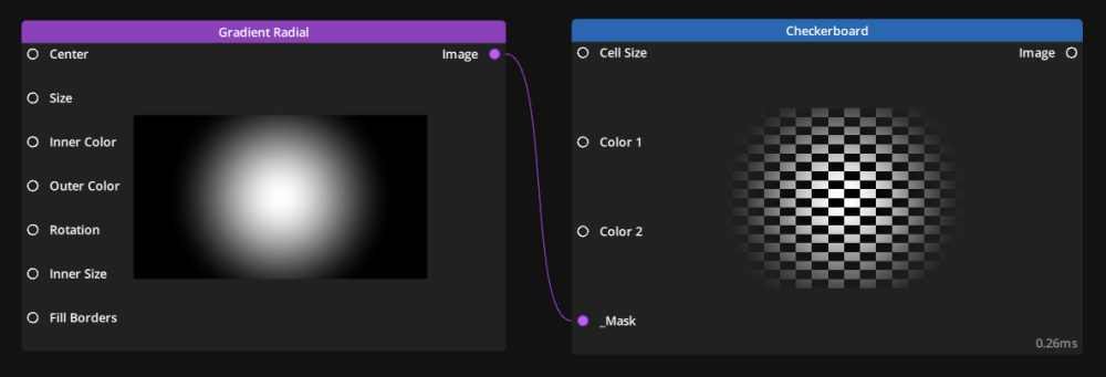
Every node in the render graph has a Mask Mode that can be toggled on by selecting the node and toggling the 
Editor panel.
This unlocks an additional Mask input pin expecting an Image type that will be used as a Mask on the content of the node. It also unlocks a Menu next to the Mask Texture where you can choose which channels to select from the Mask image to use as a Mask.
Default values at 10%
Some values have default values set as a percentage (most often 10%) of the width (sometimes height) of the graph.
This will produce different values depending on the Mode the Graph is set in.
Pixel Mode
In this case the percentage will be calculated using the value in pixel of the width (or height).
For example if your graph is set to Full HD (1920 × 1080) then the default value of 10% will be 192.
Normalized Mode
In this case, the percentage will be calculated using 1 as a max value for width and for height. The pixel value underneath will be ignored.
For example, regardless of the resolution of the graph, a default value of 10% will be 0.1.
Need more help with this?
Don’t hesitate to contact us here.


